リアルタイム映像配信のための次世代輻輳制御機構の研究開発
慶應義塾大学
政策・メディア研究科
後期博士課程 80749423
松園和久
I. Introduction
The evolution of the Internet has seen a rapid growth in both users and
applications. Owing to the dissemination of high-speed broadband networks, users
are expecting to fulfill an application demand more comfortably, and
applications promote users to increase their motivation. High-quality and
high-performance realtime applications are the primary ones. Engineers are
developing high-performance streaming applications [1], [2] that can be used
easily with consumer electronic devices and ordinary PCs for the purposes of
e-learning, international symposiums, and telemedicine [3]. It is easily
expected that as the Internet evolves to higher-speed networks, these video
applications will become increasingly popular.
Typically, real-time
interactive video streaming requires the minimization of packet losses while
maintaining the highest data transmission rate under acceptable transmission
delays, to produce the best possible streaming quality. However, because
highquality and high-performance streaming flows consume a large amount of
network bandwidth for data transmission, they may compete for bandwidth with
other data flows (e.g., transmission control protocol (TCP) and/or user datagram
protocol (UDP) flows) in a shared best-effort network like the Internet, and
cause packet losses that can severely impact playback quality. The quality
degradation caused by packet loss is a critical problem, especially for
mission-critical applications such as telemedicine. The type of packet loss
caused by congested routers, which is characterized by near-random and
unpredictable behavior, is inevitable even with the future Internet, and
therefore presents a formidable challenge to high-performance streaming
applications seeking to optimize streaming quality.
TCP-friendly rate
control (TFRC) has become the de facto standard to control network congestion
[4], [5]. In accordance with the definition of TCP friendliness, TFRC tries to
maintain fairness with competing TCP flows in the same network condition while
providing a promising mechanism for a smooth data transmission rate [6], [7].
The throughput of non-TCP flows is strongly affected by the average throughput
of a conformant TCP connection under the same conditions. Since this constraint
can force a high-performance streaming flow to reduce the data transmission rate
at the expense of video quality, TFRC is not suitable for the flow to maximize
the streaming quality. In addition, when the feedback delay (i.e., the round
trip time) is large, a timely and correct estimation of network conditions
becomes an impossible task. As a result, unacceptable conditions for video
streaming (i.e., packet loss or data rate oscillations) continuously occur [8],
and they can have a negative impact on the communication quality of other
competing flows (e.g., throughput). In this context, existing approaches do not
properly control congestion to fulfill the demands of end-users wanting the
highest streaming quality.
To address the problem that TFRC fails to
maintain higher streaming quality, we propose the dynamic probing forward error
correction (DP-FEC) mechanism that provides a promising method for achieving
higher streaming quality while seeking the behaviors of competing TCP flows.
DP-FEC estimates the network conditions by dynamically adjusting the degree of
FEC redundancy while trying to recover lost data packets. By successively
observing variation in the intervals between packet loss events, DP-FEC
effectively utilizes network resources. It optimally adjusts the degree of FEC
redundancy to recover as many lost data packets as possible while minimizing the
performance impact of competing TCP flows. We evaluated the DP-FEC algorithm
using an NS-2 simulator, and showed that it allows streaming flows to retain
higher streaming quality and minimizes the impact of FEC on TCP performance to
achieve TCP friendliness.
II. Requirement
High-performance realtime streaming using TFRC suffers from an unnecessary
reduction in the data transmission rate (i.e., video quality) due to improper
congestion control. Instead of using TFRC, an alternative protocol is
indispensable for high-performance real-time streaming to preserve the highest
data transmission rate and avoid a degradation of playback quality caused by
packet losses in congested networks, especially when the physical network
bandwidth is much larger than the total consumption bandwidth of
high-performance streaming flows *2. From this point of view, it is important to
protect playback quality from packet loss while executing effective congestion
control to achieve TCP friendliness.
An application level forward error
correction (AL-FEC) approach prevents retransmission delays by preventively
adding redundancy packets to the streaming data flow. Thanks to this redundancy,
a certain number of missing data packets can be recovered. Even if a certain
degree of FEC redundancy is applied to a high-performance streaming flow with
TFRC, the flow cannot improve the video quality in congested networks as
described before. However, ascertaining and controlling optimal FEC redundancy
at the highest data transmission rate is a real challenge, because 1) it is
difficult for a sender to determine the packet loss pattern at each moment (as
there is a feedback delay) and to predict the futural packet loss pattern, and
2) increasing FEC redundancy may disturb both streaming and competing flows such
as TCP when the conditions of competing flows are sensitively oscillated in the
network. The following factors are important when enhancing FEC redundancy.
1. Because failure to appropriately adjust FEC redundancy (such that FEC cannot recover lost data packets) will lead to non-recoverable data loss, FEC redundancy must be adjusted to optimize the recovery of lost data packets.
2. Controlling FEC redundancy is not inconsequential to the behavior of other flows. It is important, therefore, to estimate the network conditions and the impact of FEC on the communication quality of other flows while controlling FEC redundancy.
III. Design of Dynamic Probing FEC Mechanism
we propose the dynamic probing forward error correction (DP-FEC) mechanism to satisfy the requirements aforementioned. According to the network condition, the mechanism changes “FEC window size” (packets) to make a packet loss tolerance, while considering the impact of FEC on the performances of competing TCP flows.
DP-FEC operates mainly at the sender. A sender transmits data and FEC repair
packets over a real-time transport protocol (RTP) [9] carried on top of the
Internet Protocol (IP) and UDP. The DP-FEC collects the feedback information
transmitted over the real-time transport control protocol (RTCP) delivered by a
receiver, then adjusts the degree of FEC redundancy using feedback information
about packet losses. The data transmission rate, which depends on the video
format preliminarily assigned, is maintained during transmission.
DP-FEC
leverages an application level forward error correction (AL-FEC). In AL-FEC, n ?
k repair packets are added to a block of k data packets. We consider maximum
distance separable (MDS) codes such as Reed-Solomon codes [10] which can recover
all of the missing packets from any set of exactly k packets. Here, we define
the number of repair packets as the “FEC window size,” indicated by “n ? k”. If
the code parameters, the FEC window size and n, are appropriately set in the
event of packet losses, a receiver may recover all of the missing data packets
within a block. DP-FEC changes the FEC window size in a fixed FEC encoding block
length n during transmission. Furthermore, all of the generated data packets are
stored once in the FEC encoding block buffer. Depending on the FEC window size,
the number of data packets stored in the FEC encoding block buffer will vary.
DP-FEC is designed as an end-to-end model in consideration of the following
criteria:
1. Utilizing network resources effectively, the FEC window size during data transmission is increased to make a packet loss tolerance as high as possible. At the same time, network estimation for congestion control can be conducted.
2. In accordance with the network estimation, DP-FEC adjusts the FEC window size to minimize the impact of FEC on the performances of competing TCP flows.
Congestion Estimation Function
The DP-FEC algorithm consists of
three components: 1) the congestion estimation function, 2) repeating congestion
estimation, and 3) the FEC window size adjustment function. Next, we describe
the algorithm in detail and the parameters used.
The decision to adjust the
FEC window size can be summarized as follows:
1. If no congestion is sensed, the FEC window size is increased except when the FEC window size is already at its maximum.
2. If congestion is sensed, the FEC window size is decreased except when the FEC window size is at its minimum.
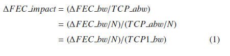
The DP-FEC recognizes above a certain degree of FEC impact on competing TCP performances as an indicator of network congestion. This means that the DP-FEC does not just use packet loss as a congestion indicator, but allows a certain level of packet loss during transmission. Here, we assume that a DP-FEC flow competes with TCP flows in the same bottleneck link, and define FEC impact as a ratio of FEC bw to TCP abw; FEC bw is the consumption bandwidth of FEC repair packets that a DP-FEC flow adds per unit time, and TCP abw is the available bandwidth that existing TCP flows can utilize per unit time. Thus, in competition with N TCP flows, the change in the degree of FEC impact (ΔFEC impact) caused by added ΔFEC bw is given by:
where TCP1 bw is the data bandwidth that one TCP flow consumes. According to TCP1 bw and N, the FEC impact on the TCP performances varies. TCP1 bw can be estimated as follows [4]:
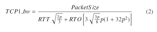
where PacketSize is the size of sending packet (bytes); p is the loss event rate; RTT is the Round Trip Time (sec); RTO is the retransmission timeout value (sec). If we can know N, ΔFEC impact can be estimated. However, N changes from moment to moment, and it is naturally hard for an end system on an end-to-end model to precisely know N at the right time. DP-FEC approximates ΔFEC bw/N by successively changing FEC bw and observing the loss interval (LI) defined as the interval of time between packet loss events. An occurrence of more than one packet loss within a specific time is recognized as a single packet loss event. In order to approximate ΔFEC bw/N, we now focus on the steady-state behavior of one TCP flow adopting the well-deployed AIMD algorithm [11] known as a mechanism for the remarkable stability of the Internet [12]. We assume that when a TCP flow observes more than one packet loss event during an RTT that results in halving the congestion window size, a DP-FEC flow also observes the same packet loss event. Since the TCP flow adopts the AIMD algorithm, LI can be approximated as follows:
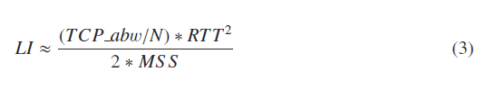
where MSS is the TCP maximum segment size (bytes). When DP-FEC adds ΔFEC bw, ΔLI can be approximated using Eq. (3), as follows:
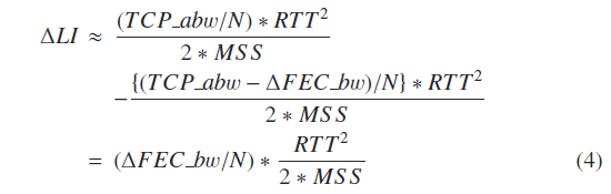
Using Eqs. (1), (2) and (4), we can approximate ΔFEC impact as follows:
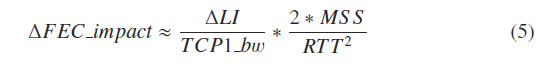
DP-FEC estimates ΔFEC impact using an observed ΔLI. An observation of a
larger value of ΔLI implies that the increasing FEC window size has a more
negative impact on TCP performances by reducing TCP abw. DP-FEC recognizes
network congestion when an estimated ΔFEC impact exceeds Threshold FEC Impact.
The value of Threshold FEC Impact in DP-FEC is set to 0.1. Since an observed ΔLI
is influenced by packet loss patterns that vary according to ever-changing
network conditions (e.g., the number of competing TCP flows and the available
bandwidth), precisely estimating ΔFEC impact is naturally difficult. Therefore,
by successively observing ΔLI while changing the FEC window size, DP-FEC
evaluates whether ΔFEC impact exceeds Threshold FEC Impact or not. Although this
strategy leads to low responsiveness to a change in network conditions, DP-FEC
can effectively utilize network resources by adding FEC repair packets while
considering the impact of FEC on TCP flows.
As Eq. (5) shows, the estimation
of ΔFEC impact depends largely on RTT that competing TCP flows have, since TCP
performance generally relies on RTT. If the RTT value is large, DP-FEC tends to
conservatively behave and keep a small FEC window size even in slightly
congested networks. This situation causes a number of non-recovered data packets
without effectively utilizing network resources. To avoid such a behavior,
DP-FEC estimates ΔFEC impact assuming that all competing TCP flows have RTT =
0.01 (sec). Thus, in competition with TCP flows with RTT > 0.01, the DP-FEC
tends to keep a larger FEC window size due to the underestimation of ΔFEC
impact.
Repeating Congestion Estimation
A DP-FEC receiver sends feedback
information at constant time interval (SYN time), which denotes whether packet
loss happened or not during the SYN time. Multiple packet losses in the same SYN
time are considered as a single loss event. As described before, DP-FEC assumes
that 1) both a DP-FEC flow and TCP flow observe the same packet loss event
during an RTT and 2) all competing TCP flows have RTT = 0.01 (sec). Thus, the
value of SYN time in DP-FEC is set to 0.01 (sec). A sender receives feedback
information at the SYN time interval, and calculates the sample loss interval
(SampleLI), the minimum value of which is equivalent to 0.01 (sec). Using the
Exponential Weighted Moving Average (EWMA), current LI is calculated as follows:
LI = α x LI + (1 - α) x SampleLI. DP-FEC uses the smoothing factor α = 0.9, and
estimates ΔFEC impact with the observed variation of LI (ΔLI) at the constant
interval (ResTime). The ResTime relates to the tradeoff between the
aggressiveness (i.e., increasing rate of FEC window size) and estimation
accuracy of FEC impact (i.e., TCP-friendliness). In an ever-changing network
condition, the appropriate setting of ResTime value is quite difficult. In this
paper, we set ResTime to 0.16 (sec) based on our comprehensive simulation
results as of now.
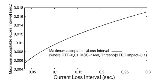
The above figure shows the relation between the current LI and maximum acceptable ΔLI, where MSS=1,460 (bytes), RTT=0.01 (sec). If an observed ΔLI exceeds the maximum acceptable ΔLI, a sender recognizes an occurrence of network congestion (i.e., ΔFEC impact > 0.1). Note that if a network condition drastically becomes worse (e.g., due to an occurrence of bursty traffic), LI severely decreases. If this situation continues, DP-FEC needs to decrease the FEC window size in order to avoid congestion collapse. Therefore, DP-FEC also recognizes a network congestion when LI becomes less than the minimum value (MinLI). Every time a sender receives feedback information, the current LI is calculated and judged to be below MinLI. When DP-FEC uses an extremely-low value of MinLI, the attainable FEC window size becomes large even in highly congested networks due to the slow response to the network congestion. Such a situation causes a significant degradation of the performances of competing TCP flows. To avoid it, we set MinLI to 0.035 (sec) based on our simulation experiments as of now.
FEC Window Size Adjustment Function
DP-FEC recognizes network
congestion when estimated ΔFEC impact exceeds Threshold FEC Impact or current LI
falls below MinLI. In DP-FEC, AIMD algorithm is used to adjust the FEC window
size. FEC window size (Fwnd(t)) in packets is given by:
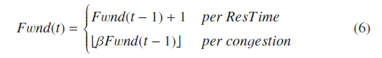
During no congestion, Fwnd is linearly increased. During congestion, DP-FEC immediately decreases Fwnd using multiplicative factor β. DP-FEC with a low value of β tends to fail to recover lost data packets in continuously congested networks, because the attainable FEC window size becomes small. Since 1) DPFEC should try to recover data loss as much as possible, and 2) by estimating and controlling ΔFEC impact, DP-FEC can avoid a negative impact on TCP performances in network conditions where added FEC redundancy significantly disturbs TCP performances, DP-FEC sets β to a relatively high value, 0.8 (i.e., more than 0.5).
IV. Evaluation
Simulation Setup and Performance Metrics
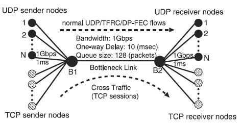
Using an NS-2 simulator extended with DP-FEC module, we performed experiments
using the dumbbell topology shown in Fig. 1. The bandwidth and propagation delay
of the bottleneck link between B1 and B2 were set to 1Gbps and 10ms,
respectively. A drop-tail queuing was used at the router, and the queue length
size in packets was set to 128. Each sender and receiver were connected to the
bottleneck link through the 1 Gbps access link with a propagation delay of 1ms.
The packet size was set to 1,500 bytes for all connections. Each simulation ran
for about 120 seconds.
In all simulation experiments, a DP-FEC sender takes
the same algorithm for sending data packets. It transmits smoothed data packets
at a rate of 30 Mbps. As a practical matter, both the FEC encoding block length
and the maximum FEC window size should be determined by the acceptable FEC
encoding/decoding time for the streaming application. Here, we set the FEC
encoding block length to 127 and the maximum FEC window size to 63, modeling a
real environment.
As the DP-FEC performance metrics, we observed 1) the
average residual data loss rate of DP-FEC flows (i.e., the rate of nonrecovered
data packet) and 2) the average throughput of competing TCP flows. The metric of
the average residual data loss rate of DP-FEC flows was compared with those
observed when we used a normal UDP flow at a rate of 30 Mbps or a TFRC flow[4]
under the same network condition. As TCP friendliness index (TFindex), we use
the result of the average throughput of TCP flows observed when they compete
with TFRC flows, and define TFindex as follows:
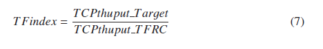
where TCPthuput Target is the result of the average throughput of TCP flows
competing with normal UDP flows or DP-FEC flows; TCPthuput TFRC is the result of
the average throughput of TCP flows competing with TFRC flows under the same
network condition.
We used Short-livedTCP flows using a NewReno. Short-lived
TCP flows arrive at the bottleneck link, as a Poisson process with an average
rate of r_tcp flows per second. The size of each TCP flow follows a Pareto
distribution with an average of s_tcp packets and shape parameter 1.5. Here, we
define the load of short-lived TCP flows as ρ_tcp = r_tcp x s_tcp. Long-lived
TCP flows are persistent in the network.
Competition with Short-lived TCP Flows
We evaluated the DP-FEC
performance in competition with short-lived TCP flows. The load of short-lived
TCP flows (ρ tcp) was set to 25%, 50% and 75% of the bottleneck link capacity.
In addition, the number of UDP streaming flows (i.e., TFRC, normal UDP or DP-FEC
flows) was changed from 1 to 10.
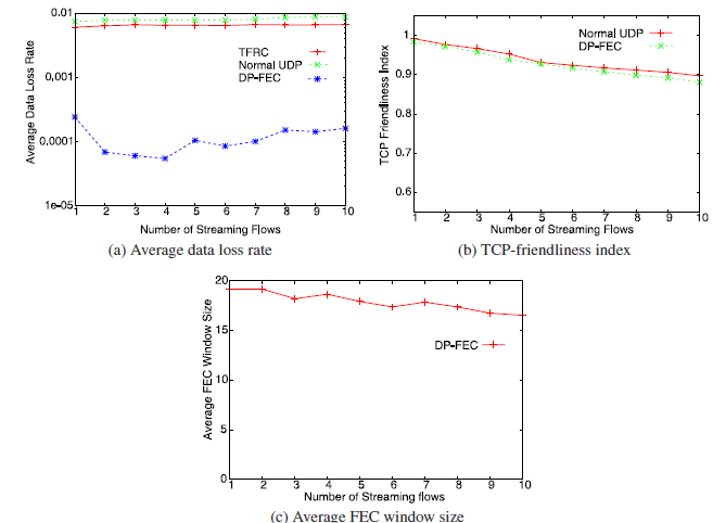
As shown in Fig. 2 (a), the average data loss rates of DP-FEC flows under 25%
load of TCP flows are considerably improved by added FEC redundancy, compared to
those of TFRC or normal UDP flows. In addition, Fig. 2 (b) shows that the TCP
friendliness indexes of both normal UDP and DP-FEC flows are maintained at more
than approximately 0.9, which means that DP-FEC flows add a well-coordinated
degree of FEC redundancy by effectively utilizing network resources that
competing TCP flows cannot consume. In Fig. 2 (c), we can see that the FEC
window sizes are almost the same (between 17 and 20) regardless of the number of
competing DP-FEC flows, because FEC impacts that each DPFEC flow estimates
during transmission are not largely different (i.e., there is little difference
in the available bandwidth for TCP flows in each test). Because of an occurrence
of packet losses caused by a behavior in slow start phase of generated
short-lived TCP flow, the average FEC window size is suppressed to below 20.
TFRC flows in each test also observe packet losses caused by a slow start phase
of generated short-lived TCP flow, and reduce the data transmission rates to
about 6Mbps. As opposed to a TFRC flow, a DP-FEC flow suppresses the average
data loss rate and preserves the highest data transmission rate while achieving
high TCP friendliness index.
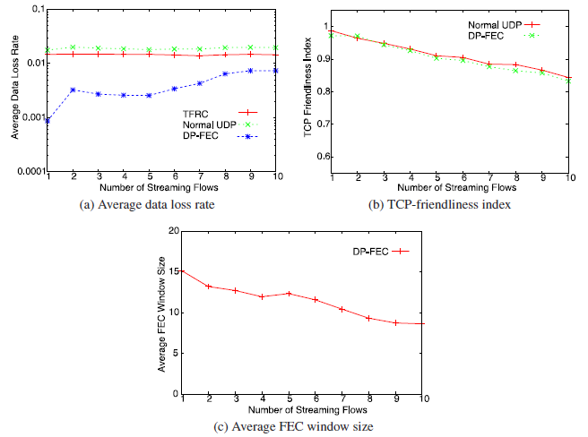
When ρ_tcp is 50% of the bottleneck link
capacity, the average data loss rates of TFRC and normal UDP flows becomes more
than 1%, as shown in Fig. 3 (a). On the other hand, owing to added FEC
redundancy, the average data loss rates of DP-FEC flows are suppressed to below
1%. In addition, Fig. 3 (b) shows that although the TCP friendliness indexes of
both normal UDP and DP-FEC flows decrease with an increase in the number of
streaming flows, DP-FEC flows in each test retains more than approximately 0.85%
of the TCP friendliness index. In Fig. 3 (c), we can see that as the number of
DP-FEC flows increases, the average FEC window size gradually decreases to about
9. This is because, under 50% load of TCP flows, DP-FEC flows tend to experience
continuous packet loss and estimate higher FEC impact with an increase in the
number of DP-FEC flows. The continuous packet loss leads to an increase in
average data packet loss rate, as shown in Fig. 3 (a).
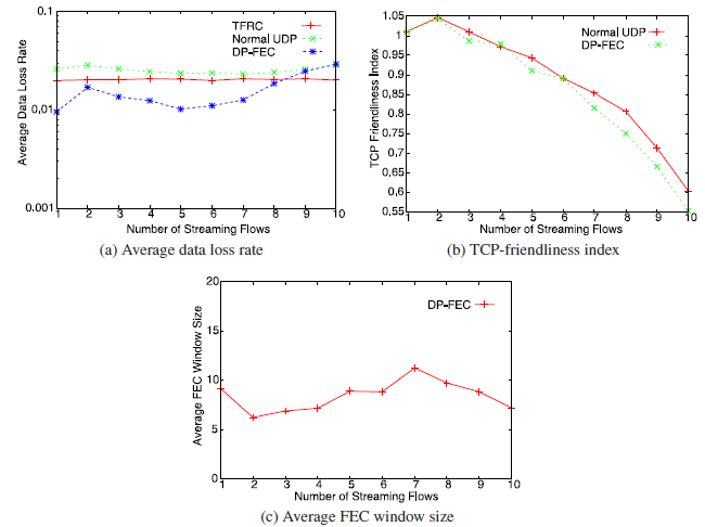
When ρ_tcp is 75% of
the bottleneck link capacity, the average loss rates of DP-FEC flows are
slightly improved except when the number of DP-FEC flows is more than 8, as
shown in Fig. 4 (a). In Fig. 4 (b), we can see that as the number of streaming
flows increases, the TCP friendliness indexes of both flows of Normal UDP and
DP-FEC severely decrease because of a reduction in the available bandwidth for
heavy short-lived TCP traffic. Due to the continuous packet loss caused by heavy
short-lived TCP traffic, the average FEC window sizes are suppressed to between
5 and 10, as shown in Fig. 4 (c). Since DP-FEC is designed to minimize FEC
impact defined as a ratio of the consumption bandwidth of FEC repair packets to
the available bandwidth for TCP flows, the TCP friendliness indexes of DP-FEC
flows become approximately the same as those of normal UDP. Therefore, in a
situation in which a normal UDP flow severely decreases the TCP friendliness
index, a DP-FEC cannot retain a higher TCP friendliness index.
V. Conclusion
we proposed the DP-FEC that effectively achieves streaming quality for a
high-performance real-time streaming. This mechanism tolerates packet loss in
the network through the adjustments of the FEC window size while examining
network congestion. By successively observing variation in the intervals between
packet loss events, DP-FEC effectively utilizes network resources and adjusts
the degree of FEC redundancy while minimizing the impact of FEC on the
performance of competing TCP flows. We verified the efficiency of DP-FEC using
an NS-2 simulator, and recognized that DP-FEC retains high streaming
quality.
In our future work, we will make more investigation to optimally set
a parameter such as Threshold FEC impact according to network conditions. Then,
we will evaluate the DP-FEC mechanism competing with more high-performance
streaming and TCP flows in complex and higher bandwidth networks. This
evaluation will improve the DP-FEC algorithm, and then accelerate deployment of
high-quality streaming applications over future heterogeneous networks.
Reference
[1] Ogawa, A., Kobayashi, K., Sugiura, K., Nakamura, O. and Murai, J.: Design and implementation of DV based video over RTP, Proc. International Packet Video Workshop (PV 2000) (May 2000).
[2] Bao, C., Li, X. and Jiang, J.: Scalable Application-Specific Measurement Framework for High Performance Network Video, Proc. ACM NOSSDAV ’07, Urbana, Illinois USA (2007).
[3] Nakashima, N., Okamura, K., Hahm, J.S., Kim, Y.W., Mizushima, H., Tatsumi, H., Moon, B.I., Han, H.S., Park, Y.J., Lee, J.H., Youm, S.K., Kang, C.H. and Shimizu, S.: Telemedicine with digital video transport system in Asia-Pacific area, Proc. 19th International Conference on Advanced Information Networking and Applications (Mar. 2005).
[4] Floyd, S., Handley, M., Padhye, J. and Widmer, J.: Equation-based congestion control for unicast applications, Proc. ACM Comput. Commun, Vol.30, No.4, pp.43-56 (Oct. 2000).
[5] Floyd, S., Handley, M., Padhye, J. andWidmer, J.: TCP Friendly Rate Control (TFRC): Protocol Specification, RFC 5348 (Sep. 2008).
[6] Seferoglu, H., Kozat, U.C., Civanlar, M.R. and Kempf, J.: Congestion state-based dynamic FEC algorithm for media friendly transport layer, Proc. International Packet Video Workshop (PV 2009) (May 2009).
[7] Feng, J. and Xu, L.: TCP-Friendly CBR-Like Rate Control, Proc. IEEE ICNP (Oct. 2008).
[8] Zhang, Y. and Loguinov, D.: Oscillations and Buffer Overflows in Video Streaming under Non-Negligible Queuing Delay, Proc. ACM NOSSDAV ’04, Cork, Ireland (2004).
[9] Schulzrinne, H., Casner, S., Frederick, R. and Jacobson, V.: RTP: A Transport Protocol for Real-Time Applications, RFC 3550 (July 2003).
[10] Rizzo, L.: Effective erasure codes for reliable computer communication protocols, Proc. ACM Comput. Commun, Vol.27, No.2, pp.24-36 (Apr. 1997).
[11] Chiu, D. and Jain, R.: Analysis of the increase and decrease algorithm for congestion avoidance in computer networks, Comput. Netw. ISDN Syst. J., Vol.17, No.1, pp.1-14 (June 1989).
[12] Papadimitriou, P. and Tsaoussidis, V.: A rate control scheme for adaptive video streaming over the Internet, Proc. IEEE ICC ’07, Glasgow, Scotland (June 2007).